design
The design of COMPACT ensures the feasibility of the scientific research questions and consists of following main components:
- Zyflex plasma chamber with following properties
- Large chamber volume
- Variable electrode distance
- Low minimum gas pressure
- 4-channel RF generator
- Multiple particle dispensers
- 2D imaging system
- 3D imaging system
- Plasma glow imaging and spectrometer
- Laser particle manipulation
- UV particle manipulation
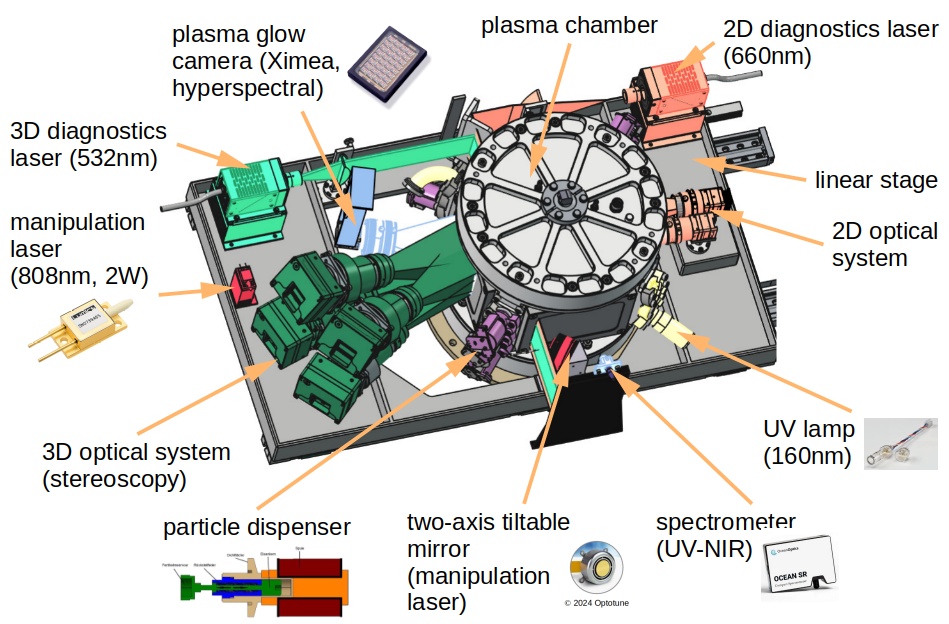
Zyflex plasma chamber
The Zyflex plasma chamber (“cylindrical and flexible”) is the heart of the experiment where the plasma is generated and the dust is trapped in the plasma volume. The chamber volume has an inner diameter of 220 mm diameter and 80 mm height. Four wide side windows (140 mm x 100 mm) enable generous optical access to the chamber. The working gas, typically argon, is led into the chamber via a flow controller. Typical operating pressure can be controlled between 0.1 Pa and 100 Pa by a turbo pump and butterfly control valve. Gas inflow and outflow are through the top and bottom lids of the chamber.
The Zyflex chamber is equipped with two pairs of electrodes in a parallel-plate geometry between which the plasma is ignited. Each electrode pair consists of an inner disk electrode of 80 mm diameter and and an outer ring electrode of 83 mm inner diameter and 114 mm outer diameter. The two electrode pairs can be moved up and down ensuring a maximum electrode separation of 80 mm and a minimum separation of 20 mm. Hence, the plasma and dust cloud volume can be drastically changed during plasma operation. The four electrodes are powered individually by a 4-channel RF generator.
Further, the side walls can host up to 12 ports. One port will be used for gas pressure monitoring, two others for the UV lamp and its beam stop. The remaining 9 ports will house the particle dispensers.
4-channel RF generator and arbitrary function generator
COMPACT is equipped with a 4-channel RF (radio-frequency) generator. This generator provides independent sinusoidal RF voltages at a frequency of 13.56 MHz for each of the four electrodes (upper and lower disk electrode and upper and lower ring electrode). The amplitude and relative phase of the RF voltages can be chosen individually for each of the four electrodes. The maximum output power per channel is 4 W.
In addition, all channels can be switched on and off individually with a minimum duty cycle of 10 µs.
The RF signals are coupled to the electrodes via a pi-type matching network. It is also planned that the electrode self-bias voltages can be modulated by low-frequency signals. There, arbitrary voltage waveforms with amplitudes up to 100 V and frequencies up to 1000 Hz can be applied through the matching network to each of the electrodes.
Mean values of the applied RF voltages as well as short sequences of highly-resolved voltage waveforms will be measured, recorded and stored.
The RF and arbitrary function generators will provide a versatile tool to manipulate the plasma properties and hence the dust cloud properties. Experiments on parabolic flights indicate that extended, homogeneous and void-free dust clouds can be produced under suitable plasma excitation waveforms.
Multiple particle dispensers
The particle dispensers are electromagnetic shakers. The tip of the dispenser carries a small housing filled with the dust. The container is covered by a sieve that is selected according to the dust size to ensure that on the one hand sufficient amounts of dust are released into the plasma and on the other hand that particle agglomerates are suppressed.
Nine dispensers with different particle sizes and particle geometries are foreseen.
2D imaging system
The 2D imaging system is intended to record the dust particles and their motion in a thin slice of the particle cloud. For that purpose, a laser beam at a wavelength of 660 nm is expanded to a sheet of about 250 µm width and 80 mm height. This laser sheet illuminates the particles in the central slice of the dust cloud. The scattered laser light is then recorded by two cameras under an angle of 90°. The cameras will be equipped with filters adapted to the laser wavelength.
The first camera, the “overview camera”, records the particles in the full region between the electrodes covering an area of 160 mm width and 80 mm height. The camera has a sensor of about 9 Mpixel with digital resolution of the order of 40 µm/pixel. The frame rate will be a maximum of 95 fps. This overview camera allows to capture the overall behavior of the cloud.
The second camera (“detail camera”) covers a field of view of 80 mm width and 80 mm height at 20 Mpixel with a higher digital resolution of about 18 µm/pixel at a maximum frame rate of 109 fps. Hence, the detail camera images approximately the right half of the discharge (in the direction of view of the cameras), shifted by 10 mm over the vertical discharge axis.
The video data of the two cameras together with those from the glow camera will be recorded by an NVIDIA Jetson and U.2 or U.3 hard drives.
3D imaging system
The 3D imaging system will enable the determination of the three-dimensional particle positions and motions in a smaller subfield of the dust cloud. This will be achieved by a four-camera stereoscopic setup where the four cameras will image the same volume of the particle cloud under slightly different angles. From these different viewing directions the particle positions are reconstructed.
Here, a stereoscopic system is envisaged where each camera has a sensor with 65 Mpixel at a digital resolution of about 9 µm/pixel. The four cameras have a common usable field of view of about 85 mm width and 45 mm height in the lower left region of the discharge (in viewing direction of the cameras). The frame rate of the cameras at full resolution is about 70 fps. However, the recorded data rate will be restricted to about 900 MByte per second for each of the cameras. Thus, for each of the cameras a smaller region of interest (ROI) will be chosen that covers the same reduced field of view. The ROIs can be freely selected within the full usable field of view. Also size and frame rate of the ROI can be adapted to the required task and is only limited by the maximum data rate per camera.
This setup allows to record the particle motion in different regions of the dust cloud without the need to mechanically move the camera setup. This strongly reduces the risk of failure.
For the recordings with the streoscopic setup the dust will be illuminated with a laser beam at a wavelength of 532 nm that is expanded into a sheet of 2.5 mm width and 45 mm height. The cameras will have filters for this laser wavelength.
The video data from the four cameras will be recorded by a second NVIDIA Jetson with U.2 or U.3 hard drives.
Both the 2D imaging system and the 3D imaging system as well as their illumination lasers are mounted on a horizontal translation state that allows to move the image and laser planes through the dust cloud. The travel range of the stage will be about 70 mm. This allows to inspect different regions of the dust cloud.
Plasma glow imaging and spectrometer
The plasma glow imaging system will capture the glow emission from the argon plasma. The most intense argon (double) spectral lines are near 750 nm, 763 nm, 810 nm and 840 nm. Here, a hyperspectral camera will be used to capture the spatially resolved plasma glow. The envisaged hyperspectral camera has a 2 Mpixel sensor chip with deposited Fabry-Perot filters in 5 x 5 arrays. Thereby, 25 spectral bands in the range from about 650 nm to 950 nm are simultaneously recorded with a spatial resolution of about 400 x 250 pixels at a frame rate of about 50 fps. From this spectral, time and space resolved data information on the plasma properties can be derived, such as (relative) plasma density or temperature.
In addition, the light from the discharge is fed to a spectrometer with a wavelength range of about 200 to 1000 nm with a resolution of about 1nm.
Laser particle manipulation
A manipulation laser (2W at a wavelength of 808 nm) will be guided through one of the side windows of the Zyflex chamber. The beam diameter is about 1 mm. The beam is positioned and moved through the dust cloud via a steering mirror system. The radiation pressure of the laser beam will transfer a momentum onto the dust particles hit by the beam and therefore excites particle motion in the direction of the beam.
UV particle manipulation
UV illumination of the dust is envisaged for the manipulation of the dust charge by photoelectron emission induced by the UV radiation. For that purpose, a small-scale UV lamp with a peak wavelength of 160 nm will provide a few watts of UV radiation. It is planned to install the lamp in one of the dispenser ports of the plasma chamber.